Basic Setup
These instructions will assume a fresh setup as if this was a
newly built helicopter and this is the first time it was connected to
the radio.
MODE - Set the Mode to Model 2. This is the
configuration used in the the United States. If you are a European
pilot, this is typically a Mode 1. In Mode 2, the Left stick
controls the throttle and rudder, and the Right stick controls the
swash plate through the Aileron, Pitch and Elevation servos.
European (Mode 1) settings cause the right stick to control the
throttle & rail rudder, and the left stick to control the
swashplate. Once set, you will never again need to revisit the MODE
option setting.
TYPE – this setting tells the radio about your
type of swash plate. Refer to your model information on the type of
swash plate installed. For the TRex and EXI, Blue Ray, Copter-X and
most TRex clones using “CCPM mixing”, this is a 120
degree swash plate. The Servo linkages are connected to the swash
plate at 120 degrees apart. For the EXI model in this document, I
will select the HELI-120 option from the drop down list.
Check with your own helicopter documentation to verify the TYPE
swashplate setting. Once set, you will never again need to revisit
this option.
ENDPOINT – There are two columns of settings.
The left column is the UP direction limitation setting, and the
right column is the down limitation in percentage. Most helicopter
servos are the 60 degree type. They have a center, and can move 30
degrees Clockwise (CW) and 30 degrees Counter-Clockwise (CCW). At
this stage in the setup, set all values to 100%. Typically
you will not have to revisit this setting unless you have a
mechanical interference or some other limiting factor that you need
to prevent the servo from traveling too far. Note: the “up”
and “down” labels can be misleading. Up may not
necessarily mean Servo horn UP movement. It merely means the travel
limit in one direction (dependent upon Servo Reversal settings –
covered later).
DR – Dual Rate setup. There are ON and OFF
columns. This setting is only relevant if your radio is later
configured to utilize dual rates by associating this function with
one of the switches. Since we recommend you have one of the
switches set for Throttle Kill, and you’ll eventually probably
want to use Idle-Up/3D mode with the other switch, there are no
additional switches to provide this functionality. Dual rate can be
thought of as selecting between two “sensitivities” of
the rudder and cyclic controls. Reacting too abruptly to minor
control movements can be difficult for a beginner or pilot who needs
very precise control, while a stunt pilot may want intensely
sensitive control to perform tight rolls and loops. The pilot that
wants to loop and roll and then land on a dime would want to
control how sensitive the controls are at different points in the
flight. Thus, these fields set what percentage of full-rate is
desired in each switch position (“on” and “off”
are again misleading misnomers, since this is really an “A”
or “B” choice when either position could be the more
sensitive one). At this stage in the setup, set all the fields of
at least one selection to 100.
SUBTRIM – these settings are used to center the
servos. At this stage in the setup, set them all to zero (0).
You will revisit this option many times as you fine tune the
helicopter.
MIX – The T6Config program and FS-CT6A model
radio support 3 mixes. A “mix” is when one channel
affects another automatically, or to associate a physical
transmitter control like a switch or dial to a certain radio
channel. We will delve more into this option later in the setup,
however for this initial setup stage, change the SWITCH setting for
all three MIX settings to OFF. To do this, select the MIX 1
from the drop down list, and then select the OFF setting from the
SWITCH drop down list. Now select the MIX 2 from the list, and set
the SWITCH setting to OFF, and finally select the MIX 3 setting and
set its SWITCH setting to OFF. We will return to this option later
in the setup.
SWASH AFR – As mentioned before this is the
pitch limiter setting. It controls how far the swash plate can
travel up and down the main shaft be controlling the cyclic servos
(Cyclic servos are the Aileron, Elevation and Pitch servos connected
to the swash plate). For this stage in the setup, set all three
values to 100%. We will revisit this setting when adjusting
the pitch.
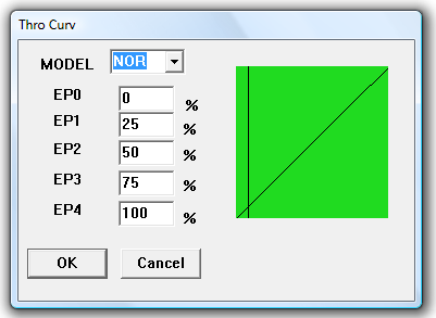
THRO CUV – The throttle curve setting has two
modes. Normal (NOR) and Idle Up/3D mode (ID). At this stage in the
setup, select the NOR option from the drop down list and set the
values to a linear curve from 0 to 100 (0-25-50-75-100).
We will return to this option later to tune the throttle to your
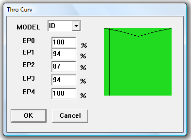
motor and flying needs. While you are here, you can set your Idle Up
throttle curve as shown below (Fig. 5). Every pilot will defend
their choice of throttle curves. This is only a basic setup
instruction. Later I will provide hints as to how you can tune these
curves to fit your needs, then you can experiment with them.
|
NOR – Normal Throttle Curve
|
ID – Idle Up/3D Throttle Curve
|
|
Fig
5
|
|
PITCH CUV – Pitch Curve settings. There are two
modes for pitch settings. Normal (NOR) and Idle Up/3D mode (ID). At
this stage in the setup, select the ID option from the drop down
list and set the values to a linear curve from 0 to 100. We
will return to this option later to tune both of the pitch curves.
SWITCH A – The A switch on this radio is the top
right On/Off toggle switch. Set the switch to the THROCUT
setting. When the switch is in the ON position, it will turn off the
signal to the ESC (Electronic Sensor Control) that control the
motor. The motor will not turn when this switch is on, providing
another level of safety while working on the helicopter or
positioning it setting. When the switch is in the
ON position, it will turn off the signal to the ESC (Electronic Sensor Control)
that control the motor. The motor will not turn when this switch is on,
providing another level of safety while working on the helicopter or positioning
it before flight. The ON position for this radio is the forward toggle position
(towards the user).
SWITCH B – The B switch on this radio is the top left On/Off toggle
switch. Set this switch to the NOR/ID setting. When the switch is in the
ON position, it will use the ID throttle curve and ID pitch curve. In the OFF
position it uses the NOR throttle curve and NOR pitch curve.
-
NOTE*** -
A lot of new helicopter pilots get into trouble with this (SW-B) switch. You
will need to use it as described in this manual for the purpose of setup.
However, before you actually fly the helicopter, I recommend that you either set
the value for this switch to NULL, or set it to DR (Dual Rate). See the section
on Dual Rate for more information.
VR(A)e pitch graph vertically). At this stage in the setup,
adjust the dial so that it is mid point between its extreme CW and
CCW positions. Typically this is with the indicator line of the dial
pointed towards 9 o'clock,
but this is NOT guaranteed to be true of your particular radio, so
find your own midpoint.
VR(B) – This dial is used for Gyro Gain
adjustment. It is not active at this time because in a previous
step, we turned off Mixing to this switch. Set its value to NULL.
You will not have to return to this setting.
At this point, you have prepared the radio for an initial
setup. This is not ready for flight, but instead ready for setting
the servo mechanically positions.
Prev
Next - Setting up the Model