Fig
9
Leveling the Swash Plate
In the previous steps, the servo horns were all mechanically and
electronically setup. The next steps is to level the swash plate.
Leveling the swashplate is the process of adjusting the other (non
referenced) linkages so that the swashplate is perfectly
perpendicular to the main shaft. You do not want to adjust the
reference linkage (our Aileron Linkage that was set to 45mm). There
are two methods to level the swash plate. The first is to use a swash
plate leveling tool. There are a number of vendors that supply this
type of tool. I use the over shaft tool (see Fig 11). The second
method is to visually inspect the swash plate for level. Obviously a
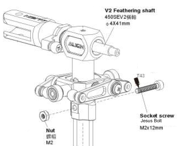
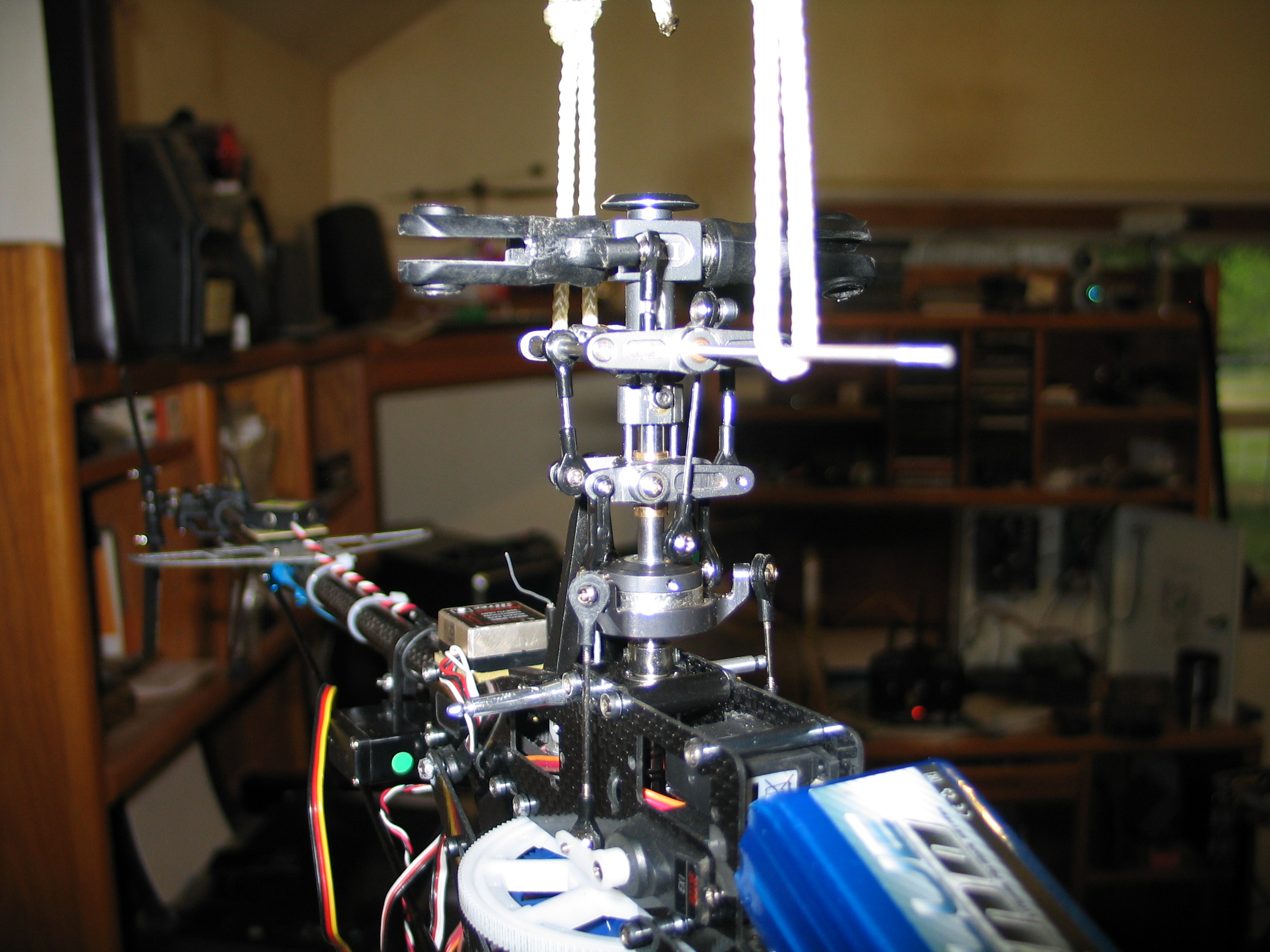
tool makes this more accurate. To use the over shaft leveling tool,
you must first remove the top “Jesus” bolt near the top
of the main shaft (Fig. 9). This is typically just below the main
head piece and below the fly-bar.
Note: The new 450 Pro swashplate has a taller center bearing that
does not allow the Sport or seV2 style leveling tool to slide all the
way down onto the perches. Some people have used a large drill bit to
acquire the additional clearance by removing some of the material
from the tool.
To remove the head, remove the Jesus bolt (you may need to apply a
hot soldering iron to the nut side of the Jesus bolt for 10~15
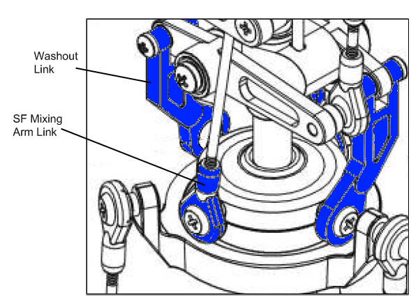
seconds to loosen the Locktite. Disconnect the washout links and SF
Mixing Arm (fly-bar control arm) links from the swash plate (Fig.
10).
Fig
10
Decouple parts (Fig 10) marked in blue from the swash plate.
Lift the head off of the main shaft. This may take some slight
force to accomplish.
Verify two motor wires are disconnected, and turn on the radio
with the Idle Up and Throttle Cut switch ON (towards you). Center the
throttle stick (left stick) and the throttle trim, and plug in the
battery to the model.
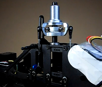
Slide the tool over the main shaft and set the tool feet on top of
the swash plate servo perches (Fig. 11)
Fig
11
Helpful Videos for using the swashplate
leveling tool.
http://www.youtube.com/watch?v=k_2RJ9YS7dA&feature=related
http://www.youtube.com/watch?v=HtwDk18gTGw
Inspect the clearance between the tool feet, and the swash plate
perches. There should be no gaps. If there are gaps, then you want to
adjust the rod linkage length to remove the gaps. You want to
maintain the servo horn 90 degree position, and get the swash plate
level at this throttle position (mid point throttle).
Note: An easy trick to keep your horns at 90 degrees, is to
temporarily change your Idle Up Pitch curve to 0, 50, 50, 50, 100.
This takes the guess work out of what is mid stick. Part of this
setup is to move the throttle stick. If you do not bring it back to
exactly the middle point, it can be frustrating. With this temporary
pitch curve setting, the throttle stick can be anywhere near center
and the horns will have the 50% position command at all times.
Addendum August 22nd 2010 –
Because of optical illusions in setting up the cyclic servo horns to
perfectly 90 degrees from the main shaft, you may have to adjust the
sub-trims very slightly. Before doing that, put in your best effort
to use the linkage lengths to get a level swashplate. When a turn of
the linkage is too much, you can resort to using sub-trim to get the
swashplate perfect. The tiny sub-trim adjustment will compensate for
the optical illusion, and get your horns and swashplate perfectly
aligned.
Once you have the swash plate level at the mid stick position, you
want to slowly move the throttle all the way Up and all the way down
observing that the swash plate does not bind at the toOnce you have the swash plate level at the mid stick position, you want to slowly
move the throttle all the way Up and all the way down observing that the swash
plate does not bind at the top or the bottom of the travel. At or near the top
of the travel, inspect the swash plate for level. Do the same for the bottom. If
everything is mechanically perfect, and you have accurate (higher quality
servos) there should be no gap throughout the swash plate movement up and down
the main shaft. Try your best to get it level at all three positions. If this
turns out to be impossible due to the quality of the servos (or your main shaft
is not perfectly straight), then you can use the ENDPOINT travel limiting
settings to restrict one or more of the cyclic servos. Reduce or increase the
ENDPOINT left side column for the channel(s) that do not have a gap. If
increasing a vlaue is used, verify the servo does not extend beyond its
physicval limitations. The servo will chatter or hum (bind) if the value it too
much. The Endpoint / Travel adjustments will allow you to get all of the servos
to provide a level swashpalte at the top and bottom of travel by restricting or
extending the travel of each servo. Use the same technique at the swashplate
bottom position to remove any gaps.
Typically you are not going to run at the highest possible pitch available with
this design. The ENDPOINT limitations will most likely become a mute point once
the SWASH AFR settings are used to restrict collective pitch later in the setup. less than
what the full travel permits. Be sure that with the horns at 90
degrees, the swash plate is level, this is ultimately more important
than at the top or bottom of travel because most of your flying will
have the swashplate between ½ and ¾ of its travel.
Note: See “Setting the SWASH AFR” section below before
re-attaching the head assembly.
Once the swashplate has been leveled you should install and
tighten the servo horn screws.
Unplug the model from the battery, and reassemble the head to the
main shaft. Remember to apply Blue Locktite to the end of the Jesus
bolt after you have pushed it through the main shaft and before
attaching the nut. Note: If your Jesus bolt is bent or damaged,
replace it. A bent Jesus bolt means it has been stressed. It is
normal for a Jesus bolt to become deformed with a lot 3D flying.
Periodically check the condition of this extremely important bolt,
and replace it when found to be deformed. If it ever lets go in
flight, you will understand why it is called the “Jesus”
bolt.
At this point you should have a level swash plate that has been
mechanically trued. If you could not get it perfectly level, you will
still be able to fly it, but you will have to manage the effects.
Note: if it is not perfectly level, just be aware that on punch outs,
the model may exhibit symptoms of moving off in one direction.
Verify the Mixing Arms, fly-bar cage, SF
Mixing arms are all level.
Addendum August 22nd 2010 –
Going from the ground up. Every
EXI head I have worked on came to me with the linkages set to the
wrong lengths. All paired links must be exactly the same length
center ball to center ball. In this section I will describe the setup
after the swashplate is level.
Note – during this procedure, you will detach and
reattach links. I prefer to remove the ball screw instead of using
the link pliers. The more times you use the link pliers, the more
damage is done to the plastic link.
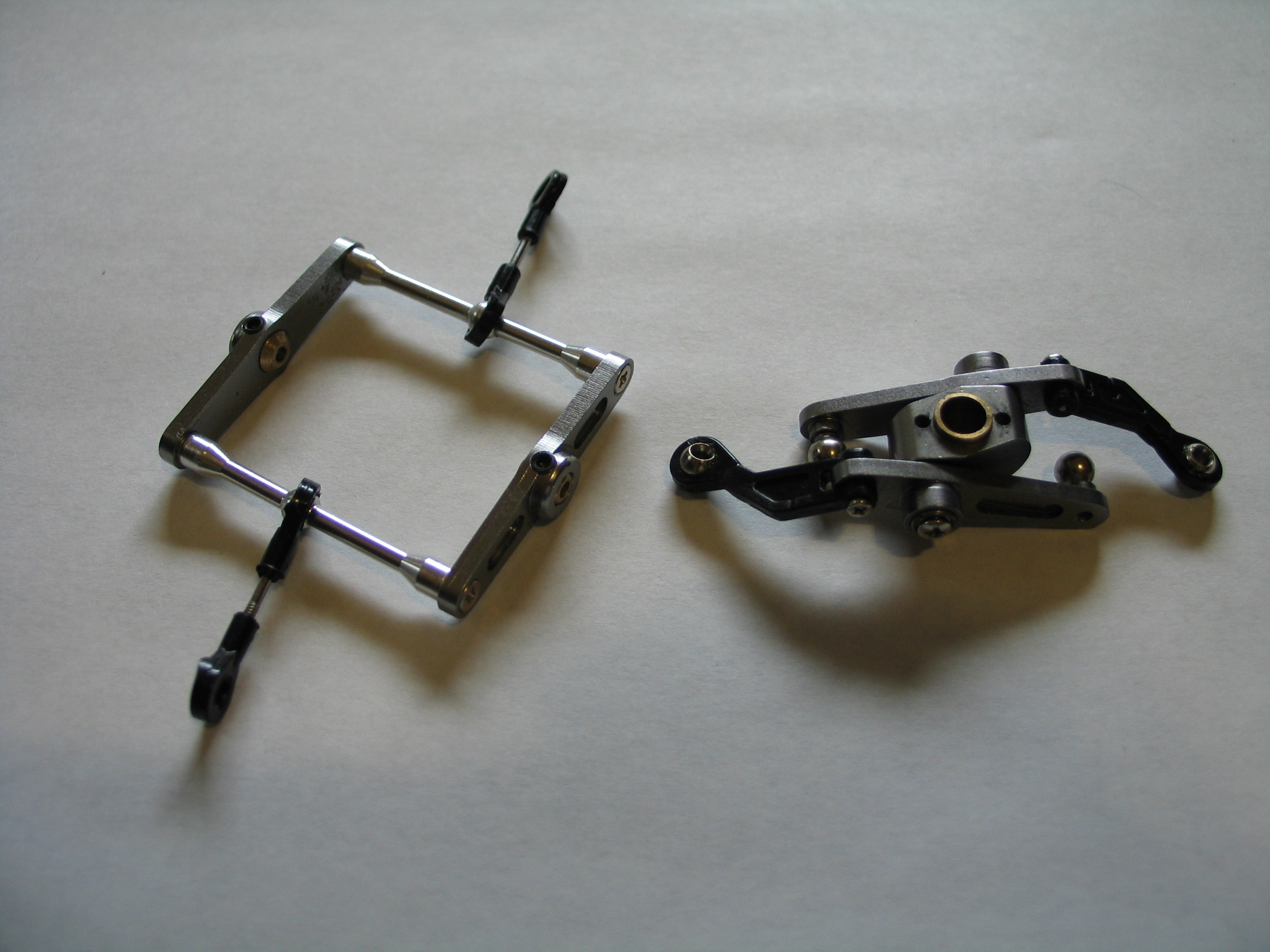
First thing I do is pull the flybar
out, and loosen one side of the flybar cage and pull the cage off the
head assembly. Then I remove the flybar links from the lower SF
mixing arms.
Fig
11a
Next, place the washout base onto
the main shaft with the longer end of the brass bushing down towards
the swashplate. Attach the washout arms to the swashplate using
Loctite on the screw ends. Use caution not to get any Loctite on the
ball, or on the swashplate. Place the screw through the ball, and put
a drop of Loctite on a flat coffee stirrer, then use the coffee
stirrer to dab a little Loctite on the end of the screw for a light
covering of three threads. Use a napkin to remove any excess.
Now measure the flybar links. From
center ball to center ball they should be approximately 23.5 mm
(0.925 in.). Adjust the links to be the exact same. Some heads (non
TREX/EXI V2) are different and may require a different length. The
important part is they are exactly the same length. If they are
unequal; the flybar will not be level with the lower SF arms and
swashplate. The result will cause head vibration, undue stress on the
servos, over stress of the upper Jesus bolt and the model will tend
to not be stable in a hover.
These links determine the center
position of the swashplate on the main shaft. The lower SF mixing
arms and the flybar cage need to be level with the swashplate at 50%
collective. Before reattaching the flybar cage to the main head, go
ahead and measure the long links. These links control the top SF
mixing arms and ultimately the pitch. The V2 link from center ball to
center ball is 42mm (1.65in).
Once the links are set to the same
length, you can reattach the flybar cage to the main head. Go ahead
and Loctite the flybar cage screws. It is usually easier to slide the
flybar through the cage and main shaft before tightening the flybar
cage screws. Now slide the head onto the main shaft, slide the Jesus
bolt through the head and main shaft and snug the nut. Do not tighten
or use Loctite yet.
Attach the flybar links to the SF
Mixing arms. Turn on the radio and connect power to the receiver
(plug the battery into the ESC). The radio should still be set to 50%
collective (throttle) with the trim slider centered as in the
previous steps. Use a ruler to check for the level of the flybar
cage. Both mixing arms and flybar cage should be level (perpendicular
to the main shaft). If the flybar cage is not level, then adjust the
appropriate link to get the flybar cage level. It is more important
in this stage to get the flybar cage level. Once the flybar cage is
level, then determine if the lower mixing arms are level. If the
lower mixing arms are not level, then you have two choices. You can
either adjust all three servo links to raise or lower the entire
swashplate or adjust the two flybar cage links. However before making
any adjustment, check the amount of clearance between the Mixing
block and the head (where the guide pins come out). Put the throttle
stick all the way up, and move the trim slider all the way up and
check the clearance. If you have about an 1/8th
inch between the brass bushing and the bottom of the head block, then
you should adjust the flybar cage links to get the mixing arms level.
If you do not have clearance, then you need to lower the swashplate
by adjusting all three servo links equally. If you adjust the cyclic
servo linkages, then you should go back through the swashplate
leveling procedure with the new lengths. Remember to reset the
throttle stick to 50% and the trim slider make to center.
Note, a little trick that helps
in getting the flybar and lower mixing arms level is to suspend the
helicopter from the flybar so that the links, servos and all
components are holding the static weight of the helicopter. I am
using 1/8th
in cotton rope, however fishing line is a better choice. Also move
the rope or fishing line up against the flybar cage. This technique
allows you to keep the flybar from moving so that you can get
accurate measurements.
Fig
11b
Now that the swashplate is level, the
lower mixing arms are level, and the flybar cage is level, we can
move on to the upper mixing arms. Attach and snug tight one of the
long links from the upper mixing arms to the swashplate. Do not apply
Loctite yet.
The upper mixing arms need to be level.
The bottom of the upper mixing arms are straight. We will not level
against the bottom, but the center of the long link ball, and the
center of the mixing arm mounting screw. We want the blade grip link
screw to be lower than the mixing arm mounting screw to give us
adequate adjustment capability for the blade grips. The flybar
control rods make a nice point of reference.
One end of the mixing arm dips down and
is used for the Blade Grip links. When checking level, use the center
screw, and the long link screw. If both of the long links were set to
the same length 42mm (1.65in), the arms should be level. If not, then
adjust the long links equal turns until the mixing arms are level.
Suspending the helicopter from the flybar helps this measurement as
well. When the mixing arm mounting screw and the long link screw line
up with the flybar control rod (both mixing arms) then we can move on
to the blade grip link adjustments.
With our current 50% throttle
setting, and everything up to this point is level, it is time to
adjust the blade grips. We want the blade grips to be level. There
are a few ways of doing this. You can slip a long small diameter rod
(like a screwdriver) through the blade mounting holes and adjust the
links until the rod is parallel to the main shaft, or you can place a
blade sideways in the grip (thick end) and adjust the link until the
blade is level. Another way is to attach the blade normally and use a
pitch gauge to adjust the link to get zero pitch on both blades. I
do all three methods in that order.
Now that you're head is setup, you
should go back through the head, and use Loctite on all metal to
metal screws. If you find a screw that is just too tight, don't force
it. More than likely it already had Loctite applied at the factory.
Let the Loctite dry for a minimum of two hours before firing up the
motor.
Prev
Next - Swashplate AFR Settings