Servo Centering
In this next step, we are going to center the servos and verify
they are moving in the correct direction. Before making the
adjustments, lets review the purpose and concepts behind this step.
This means we intend for the control horn to be in the middle of
it’s intended travel. However, the servo horn is mounted in a
mostly random position at the factory since they don’t know
which way the servo will eventually be mounted, so this will most
likely not be anywhere near where we want it centered for your model.
The mounting position and built in tolerance of the servo may require
an adjustment to position the servo horn so that it is perpendicular
to the main shaft (parallel to the top main bearing block). The end
result is to have the linkage connecting the servo horn to the
swashplate to be exactly at a 90 degree angle (linkage will be
parallel to the main shaft).
Note: the pictures below show the servo horns attached and linkage
attached. This is to illustrate the end result after the settings are
complete.
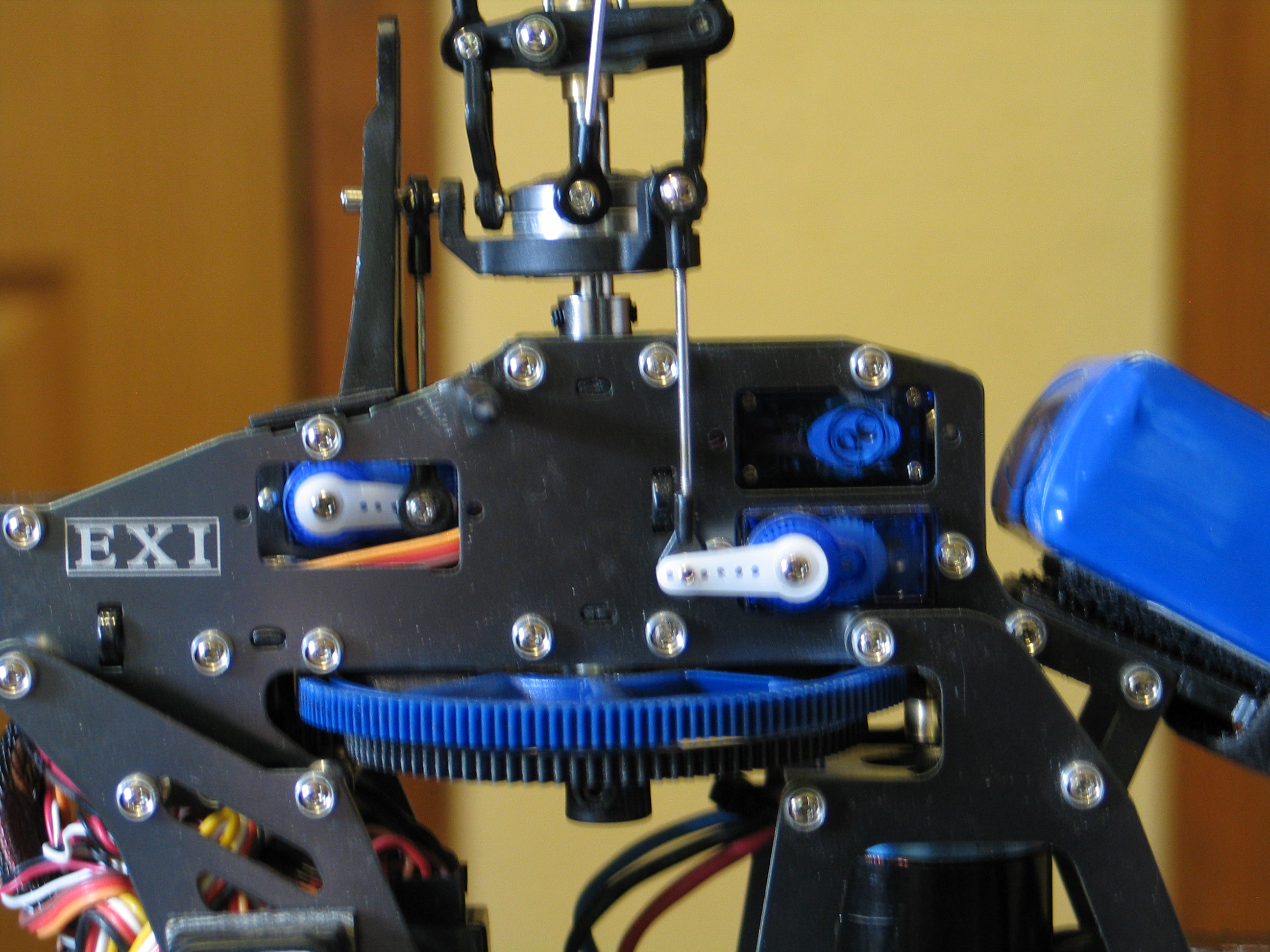
Fig
7
*Note – some models arrange the servos in different
locations and orientation. Some models such as the TREX 600 (Fig. 8)
have intermediate pivot arms and double linkage rods. The Black Hawk
450 (Fig. 8b) uses intermediate pivot arms and angled servo mounts.
The same basic concept applies. All cyclic linkages must be parallel
to the main shaft and remain parallel throughout their entire range
of travel.
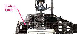
Fig
8
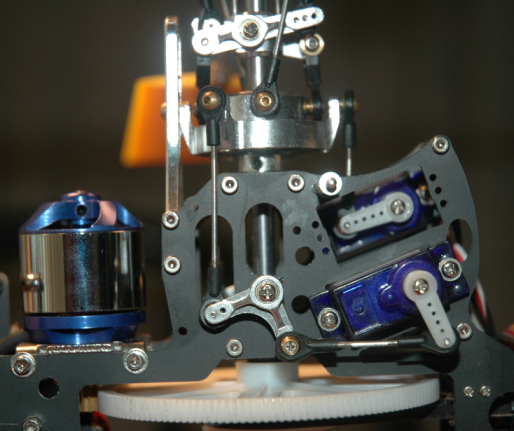
Fig 8b
Why must it be 90 degrees? This is important to understand. The
servo horn travels on an arc from the servo hub gear. The distance
the rod linkage travels is therefore not linear. The further the horn
rotates the less amount of linear rate. In other words, the first 10
degrees of horn rotation will provide more linkage movement than the
next 10 degrees, and so on. All of the servo horns must be as close
to 90 degrees to the swash plate linkage rods as possible in both
axes. If this is not obtained, the result will cause the swash plate
to tilt towards the servo that is not suppling the same amount of
travel for the same amount of signal input as the others. The model
will start to slide forward or backwards, or left or right in flight
as you change the elevation (throttle input).
This inadvertent control is annoying at best, and nearly
uncontrollable at worst, so therefore, take your time mechanically
centering your servos here and electronically perfecting them later.,
and get them perfectly centered.
Selecting the correct mounting hole for the servo is very
important. As described above, the distance the linkage rod travels
must be the same for all cyclic servos. If one servo is using the
last hole, and one is using the first hole, obviously the helicopter
will be unmanageable in flight without some creative mixing and Swash
plate AFR adjustments. This is part of what we call the mechanical
setup. Without a correct mechanical setup, the radio settings may not
be capable of overcoming the mechanically induced errors.
Which hole to use? This is (as in many other places) a trade off.
The hole farthest from the hub gives you more control range
and faster control response, but less precision and moderately more
stress on the servo motors. The hole nearest the hub gives you less
control range, slower control response, but more precision and
less stress on the servo motors. Depending just how long your
particular servo horns actually are, you may need to experiment with
which one gives you “enough” control and speed without
being “too much” or having controls physically hitting
one another at extremes of movement.
To center the servo horns, first remove the horns from the servos.
We are doing this to prevent a long servo horn, or a horn placed in
the wrong position from making contact with another object. If
contact is made, it can damage a servo gear.
Unplug TWO of the
motor wires from the ESC (A brushless motor can still run with
only one lead disconnected). We will be powering up the model and
do not want the motor to accidentally power up. Unplugging the motor
wires is cheap insurance. Don't just rely on the Throttle Kill switch
as radios can fall over, and Murphy's law takes over.
Plug the battery into the ESC and turn on your transmitter. Set
the Idle Up/3D switch (SWITCH B) into the Idle Up mode (towards you).
Set the left stick trims to center (All of the mechanical trims to
center). Place the Throttle cut (SWITCH A) towards you just to be
safe. Set the throttle stick to exactly center. The idea here is to
use the middle of the linear ID pitch curve at 50 for centering the
servos.
Note:
Throttle Trim Position during setup
This is one of
those controversial topics in this hobby. Some videos will ask you to
place the TX throttle trim to the lowest position before centering
the servos. Others will tell you to set the trim slider to the center
position.
Lets take a
moment here to examine this issue. The T6 Radio uses the same exact
potentiometer component for all 4 trim controls. This is a three wire
component where the center tap provides zero signal. Moving to one
side or the other will increase the signal output a plus or minus
value to the mixing controller electronics. At the center position
there is no input to the controller an all influence of this value is
taken out of the collective mixing logic. View the T6Config graph to
see what this position does to servo input.
If you decide to
place the throttle trim all the way to the bottom during this setup,
and line up the servo horns to 90 degrees to the main shaft, think
about what you have just done.
You have
introduced a negative value to the collective mixing controller. This
turns the servo motors about 5 degrees which comes out of the 30
degrees available for the down pitch direction. This equates to about
3 degrees of blade pitch that you have removed from the possible
negative pitch capacity.
The purpose of
this setup is to get the swashplate exactly centered between the
upper and lower limits of travel on the main shaft. You want the
servo horns to be at 90 degrees from the main shaft, and the linkages
as close to parallel to the main shaft as possible. Remember this
setup is for the mechanical alignment so that you can later make
adjustments with the radio to take advantage of pitch capacity of the
design.
Another benefit
of setting the radio throttle trim to the center position is that
when you set the pitch to zero degrees at center stick, then by
moving the trim adjustment to the bottom (after everything is setup
mechanically), you automatically get about 3 degrees of negative
pitch. Negative pitch is important in Normal mode for takeoffs and
auto rotation landings. If you use the lower trim position in this
setup step, then you will need to inject a less than 50% value
in the normal pitch curve to get the desired 2~3 degrees negative
pitch.
Where did this
controversy start? I am of the opinion that Fixed pitch pilots are at
the heart of this misunderstanding. Fixed pitch (and coaxial) pilots
desire the throttle trim to be at the bottom because it controls the
speed. An FP setup does not control the collective pitch like in a
CCPM mechanism. So I think this is a carry over from so many FP
pilots getting into CCPM, and sticking with old habits.
Note: Another popular option is to temporarily set the Idle Up
Pitch Curve to 0,50,50,50,100 so that you won't have to guess what is
exactly center stick. With this pitch curve setting, anywhere around
center stick will provide 50% total collective pitch and provides
very consistent checks.
The cyclic servos will find their centers. Press-fit (but to not
screw in) a servo horn to the Aileron servo gear hub. The Aileron
servo (typically the right side of the model) is the reference point.
Everything else will be adjusted according to this servo. Place the
horn on so that it is 90 degrees as possible to the linkage. Don’t
worry if it doesn't line up at a perfect 90 degrees yet. Due to the
size of the servo hub’s teeth, this is unlikely to be perfect
yet, and we will use the radio SUBTRIM settings to obtain an exact
position as part of the swashplate leveling exercise. Do not connect
the linkage yet.
Optical Illusion
Perfection is the name of the game for setting up your helicopter.
Eyes can play games with you when finding that perfect servo center
position. To help get a more accurate reading, it helps to use a
reference. The horns need to be 90 degrees to the main shaft, not the
boom or body, but the main shaft.
An easy tool to help with this is a simple credit card. The edges
are 90 degrees and it is long enough to give you a good reference. In
the picture below (Fig 8c), I am using special card (same material
and size as a credit card) to align the horn. When eye-balling the
horn, I put in +40 sub-trim. But once I used this credit card as a
reference, the sub-trim was readjusted to only +25.
Align the long end of the credit card to the main shaft, and the
short end centered on the servo hub screw, and the ball link screw.
As you can see in the photo, the eye-ball measurement was slightly
off. After the adjustment, it was perfect.
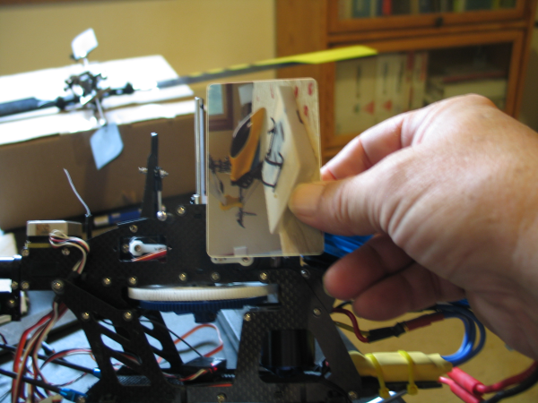
Fig.
8c
Prev
Next - Checking for Servo Direction