SW(B) Idle Up / 3D Mode
New hobbyists are intimidated by this
control. And for good reason, using the stock Idle-Up Throttle and
Pitch settings, the motor is going to jump into high speed. The pitch
will jump to the location specified by the Idle Up (ID) pitch curve
for that throttle location. The result can be a dramatic reaction by
the helicopter.
It is not advisable to start the
helicopter in 3D (Idle-Up) mode when first taking it to the field. If
you watch a Pro, he will first spin up under normal mode and lift
the helicopter into a low hover, sit it back down, and then switch to
one of his 3D modes. The reason he (or she) does this is for safety.
It is a quick check to make sure the helicopter is flight worthy
before asking it to switch into an extreme operational mode.
Starting in Idle-Up mode is hard on
the entire drive train, the motor, and the ESC. Consider the head
will instantly accelerate to 85% or higher of the total motor speed.
The blades will fold back in their grips during acceleration and may
cause an out of balance condition further subjecting your model to
extreme stress. The blades will eventually return to the correct
position due to centrifugal force.
To reduce stress on the drive train,
you can start the Helicopter in normal mode, bring the speed of the
head up slowly to mid point and then toggle the SW-B switch
(Idle-Up). Before attempting this, you should verify your NORM pitch
and ID pitch settings are not too far off at mid stick. To test the
difference, set the Throttle Cut switch (SW-A) to turn off power to
the motor. Place the throttle stick to mid stick, and toggle the
Idle-Up switch (SW-B) several times observing the amount of pitch
change. There should be little difference in swashplate movement. The
overall amount of pitch should be low. Keep in mind that the Idle-Up
throttle speed is much higher, so the amount of thrust produced with
this small pitch angle is magnified in comparison to the lower speed
of the normal switch setting.
If you are intent on starting the
helicopter in 3D (Idle-Up) mode, then use the Throttle Cut SW-A
switch to prevent the motor from turning (switch towards you). Turn
on the Helicopter power, set the throttle stick to just below mid
point (slight negative pitch), and then flip the SW-A switch
(Throttle Cut) to normal. This procedure will place the blade pitch
to just below zero before power is applied. The slight negative pitch
pushes the model into the landing skids sticking it to the ground
thereby reducing the amount of tail spin on start-up.
To minimize the stress of start-up in
either Normal or Idle-Up mode, you should use an ESC that supports a
slow start-up feature. The Align and Castle Creations ESC models use
a very slow ramp feature to virtually eliminate the start-up stress
on both the mechanical and electronic components. If you have one of
these advanced ESC models, you can configure the ESC to lock out this
slow start-up mode once the motor reaches operating speed. The
lockout prevents the ESC from accidentally resetting into slow
start-up during flight in case there is an electronic glitch or the
Throttle-Cut was applied as part of a stunt. If your ESC does not
have the ability to lockout this setting, then research how long the
throttle can be set to zero before ESC re-arms the slow-start
function. This will also be important information to know if you
practice “auto-rotation” landings, as using throttle kill
too long may commit you to an under-powered landing.
*Note – some ESC manufacturers
have a safety feature built in that will prevent the motor from
starting in 3D mode.
*Safety Note – NEVER stand close
to a helicopter during motor start up in Normal or 3D mode.
Note: The Norm / Idle Up switch simply
swaps settings between the available throttle and pitch curves. The
more exact meaning of this switch is Throttle-Pitch-Curve #1 and
Throttle-Pitch-Curve #2. With that in mind, you can program each set
of curves, and test each in the field to experiment with how each
curve behaves. For example, you can set both NOR and ID pitch curves
to be the same, and just change the ID throttle curve to be slightly
different than the NOR throttle curve. Switching SW-B allows you to
experiment with the different settings.
This is an excellent way to compare potential new curves, and choose
which values work best for your model and your skill level.
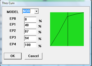
The T6 configuration uses a graphical
representation for Throttle and Pitch curves. The Throttle curve
graph can be confusing. EP0 represents bottom left stick, and EP4
represents full top throttle stick.
|
Fig
20
|
|
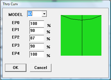
The vertical line is the throttle
stick of the radio. Move the stick and watch the vertical line move
across the graph. In the curve graphs above, the mid point throttle
is 87% for both Normal mode and Idle Up mode (Fig. 20). With the
curves setup this way, the SW(B) switch will not have a dramatic
affect when toggles at throttle mid point.
*Note – Some pilots recommend a
[NOR] throttle curve as 0,70,80,90,100 to reduce tail spin as you
lower the throttle stick. I know of pilots that use a straight curve
with all points set to 100%. DO NOT use these high throttle settings
until after you have setup the tail servo and gyro.
*Safety Note – Whatever throttle
settings you use, Never connect power to the helicopter without the
transmitter powered on, and the Throttle Cut switch set to on. When
you are ready to fly, stand back from the helicopter, and in NOR mode
left stick is all the way down, or if in ID mode set the left stick
to mid point. Switch the throttle cut switch to off. The ESC start
mode (Very Soft) will gently spin up the motor.
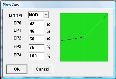
Now that the Throttle settings match,
let us turn to the Pitch curves and alter them to match at mid point
throttle.
|
Fig
21
|
|
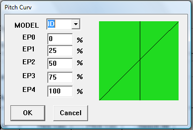
The NOR (Normal) pitch curve (Fig. 21)
has been altered so that it maintains 50% or zero pitch all the way
up to mid throttle. EP2 on both NOR and ID modes are the same. This
coupled with the altered throttle curves will provide a smooth
transition from Normal to 3D modes at mid stick.
*Note – with these adjustments,
the motor will be running at a very high speed in both normal and 3D
modes. This can be intimidating at first. With the higher speed, the
helicopter will react to pitch input with more response.
*Note – The NOR pitch curve
above is only an example of matching the mid point throttle between
normal and 3D modes. Typically the NOR curve should provide some
negative pitch below mid throttle. The negative pitch has several
advantages. It will keep the tail from spinning too much on start-up
because of the down force on the landing skids, and there will be
occasions when negative pitch will assist the pilot flying in windy
conditions by allowing the pilot to counter up drafts.
Prev
Next - Dual Rates