Blade Tracking and Pitch Curve
Up to this point all of the setup was done without the motor
connected, and using the Idle Up Pitch curve. Now it is time to set
the blade tracking, but before we do that we need to setup the Normal
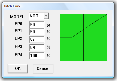
pitch curve. Select the Normal Pitch curve button, and we are going
to set the curve for a simple linear baseline for testing the blade
tracking. We want a curve that will give us enough blade and damper
flex at mid to slightly higher than mid throttle. This is typically
the hover stick location, and that means the blades are lifting the
full weight of the model. This is where we want to observe the blade
pitch.
Note: Experienced pilots can manage tracking errors in flight, and
will typically check their blade tracking in the air rather than
mounting the model to a test stand or weighting the model to the
ground. Checking it in the air is by far much safer than on a stand
or on the ground because blades can and will come off. When they do,
people and property can be damaged.
Setup the Normal settings as illustrated below (Fig 14).
Fig
14
Warnings: The following
procedure requires the motor to be running. This is a dangerous
process. Take all precautions so that you do not incur injury to
yourself or others, or property. You will need to secure the
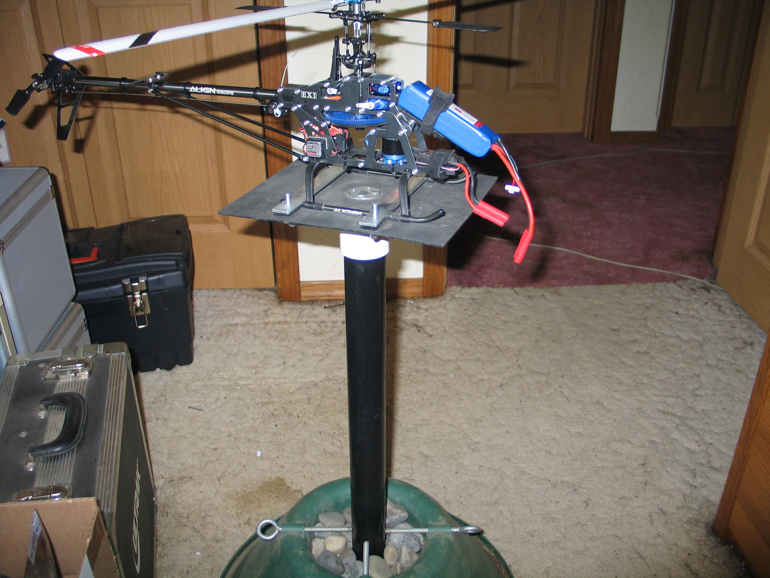
helicopter to an immovable object. I use a home made test stand made
of common parts such as 1 1/2” irrigation (PVC) pipe with a
plexiglass platform mounted with a light weight gimbel (Fig. 15).
Some users tape the landing gear to the floor, and lay a heavy
tool through the landing skids. Whatever method you use, be sure the
helicopter will not come loose. Some people perform this test in
flight. If you do not feel comfortable with performing this test with
the helicopter mounted to an immovable object, then perform the
adjustments between test flights.
Do not rely solely on the four tiny skid mounting screws to hold
your model to the ground. Place a strap through the frame under the
main gear as a precaution.
Do not trust brand new blades or blades that were used during a
crash. They may appear perfectly healthy, but tiny fractures can
instantly become a full blown disaster. When testing blades, always
stay at a safe distance the first time you engage the throttle. We
are speaking here from experience.
Fig
15
Warning: Blades are held on by
small screws or nuts. They have been known to come off at high RPM.
The first time (and actually anytime) you startup the helicopter
motor, be at a safe distance to minimize injury or damage. Where
safety goggles as you will be looking down the business end of the
blades as they rotate at a very high speed.
Power everything off. Make sure the radio's Idle Up switch (SW-B)
is set to OFF (away from you).
Set the Throttle Cut switch (SW-A) to ON (towards you). Connect
the motor wires to the ESC. Mount the helicopter to a test stand or
some immovable object (see warnings above). The objective of this
test is to adjust the blades so that each blade passes through the
same location at the same place. As the blades rotate and apply lift,
they will flex as they take on the weight of the model. The blades
must follow each other to evenly push the air. If one blade is
tracking higher than the other, it is robbing the lower blade of its
lifting capability. This results in reduced overall lift, unstable
flight, and vibration.
Set the radio left trim slide for throttle (vertical trim on the
left stick) to the bottom position. All other trims in their centered
position. Set the throttle stick to its lowest position.
Turn on the radio transmitter first. Attach the battery power
connector to the ESC connector on the helicopter. Move to a safe
distance from the helicopter. Switch the Throttle-Cut (SW-A) switch
away from you to the OFF position. Slowly power up the motor. Bring
the motor up to slightly more than mid stick. The blades should start
applying pitch and will lift in the blade grips.
Increase the throttle to about ¾ throttle and observe the
leading edge of the blades. You will notice the blades begin to flex
upwards as they take on the weight. This test must be done with the
blades producing thrust (lift) so that end play is removed from the
blade grips and feathering shaft and the dampers have the full weight
of the model.
Determine which blade is traveling higher than the other by
looking at the leading edge of the blades. The main blades travel in
a clock-wise direction looking from above the helicopter. If you are
facing the nose of the helicopter, the blades leading edge will be
coming towards you to your right (the helicopter's left side). The
reference blade we used earlier had the red decal. You want to
determine which way to move the non-referenced blade to get it
tracking with the reference blade.
Fig
16
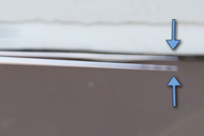
In the illustration above (Fig. 16), the lower blade is marked
with three black lines that are visible as the blades rotate at high
speed. This is observed by looking at the leading edge of the blades.
If the black marks in Fig. 16 were on our reference blade, then we
will want to adjust the opposite blade to have less pitch (leading
edge needs to be lowered). Keep in mind that our referenced blade was
used for setting our pitch, so we want to bring the other blade into
the same tracking as our referenced blade. Since the opposite blade
is tracking higher, we will need to reduce it pitch. This is done by
removing the blade grip link off of the blade grip ball, then
lengthening that link to force the leading edge downwards. Increasing
the length of this link will bring the leading edge of that blade
lower.
Rod ends are built to access the ball from only one direction. The
manufacturer will provide a mark such as a ring around the larger
hole. When adjusting the rod length, make complete turns so that the
correct hole of the rod end is facing the ball. Only adjust one turn
at a time, and retest the blade tracking.
Note: In some of the forums, remarks have been made that the small
links at the blade grips (Fig 13) are for fine adjustment, and the
long links to the swashplate are the rough adjustment. This is not
the case. The SF mixing arm is a fulcrum with the short end connected
to the blade grip with a link. With the long end of the SF mixing arm
is connected to the swashplate with the long link. The way a fulcrum
works is it takes more movement of the long end to produce a small
movement on the short end. Therefore the long end produces less
change per turn of its linkage. Less change means finer adjustment.
Adjust the proper linkage so that at ¾ throttle the blade
tips line up as they spin around.
At this point you should now have the blade tracking set so
that you only see one blade as it rotates around with enough throttle
speed to lift the helicopters weightAdjust the proper linkage so that at ¾ throttle the blade tips line up as they
spin around.
At this point you should now have the blade tracking set so that you only see
one blade as it rotates around with enough throttle speed to lift the
helicopters weight.
Prev
Next - Tail and Gyro setup