Glossary of Terms
3D / Idle Up
Throttle and Pitch Curve setting that provides higher motor speed,
and full range Plus and Minus pitch.
Aileron
This term originated from fixed wing
aircraft.
Ailerons
are hinged control surfaces attached to the trailing
edge of the wing of a fixed-wing
aircraft. The ailerons are used to control the aircraft in
roll. The two ailerons are
typically interconnected so that one goes down when the other goes
up: the down going aileron increases the lift
on its wing while the up going aileron reduces the lift on its
wing, producing a rolling moment
about the aircraft's longitudinal axis.[1]
The word aileron is French for "little wing". -
WIKIPEDIA
For the Helicopter application it
performs the same function as the fixed wing aircraft in that it will
create more lift on one side of the helicopter, and less lift on the
opposite side. This is accomplished by inducing positive blade pitch
on one side, and negative pitch on the other side. As the blade
rotates from one side of the helicopter to the other side, it will
change its pitch based on the swash plate orientation. Consider this
effect for a moment. The blade grips are constantly changing their
angle as they rotate around the head. In slow motion you would see a
washing machine effect as the blade grips rotate back and forth on
the feathering shaft as it takes a roller coaster ride around the
swash plate.
ARF – Assembly Required to Fly
This is a kit model that need to be assembled. In reality, all
models include the Ready To Fly (RFT) require that you take it apart
and reassemble with blue Locktite before flying. NEVER trust someone
else to assemble your helicopter unless they have a trusted
reputation. Do not trust an unknown factory assembly line worker to
assemble a safe and reliable helicopter. It is your investment, and
your own physical well being at risk.
Auto Rotation
The purpose of the auto rotation feature is to allow the main
blades and tail blades to continue to rotate when the main drive
motor stops or slows down. This feature allows the pilot a brief
amount of time to land the helicopter after losing main power. After
losing power, the pilot applies UP right stick to place the
helicopter in to a forward and down glide path, and continue to
control slight positive pitch with the left stick. Too much pitch,
and the blades will stall (slow down) and the helicopter will fall
out of the sky. As the helicopter approaches the ground, the pilot
will perform a flare maneuver by pulling back on the stick to level
or slightly nose up, and apply additional left stick (collective
pitch) to gently setting the helicopter to the ground.
The way auto rotation is achieved is through the use of a One Way
Bearing installed between the main gear and the auto rotation gear.
The auto rotation gear is (typically the lowest gear on the main
shaft and is bolted to the main shaft (Jesus Bolt). The sole purpose
of the main gear is to drive the auto rotation gear through the
one-way bearing. When the motor stops, so does the main gear, however
the one-way bearing allows the auto rotation gear to continue
rotating.
Belt Drive
RC Helicopters have three basic tail
drive systems.
The Belt Driven tail rotor uses a
cogged belt connected between two belt pulleys whereas one pulley is
driven from an Auto Rotation gear powered by the main motor, and the
driven tail pulley and shaft that connects to the tail rotor blade
pitch control assembly.
Blade Tracking
The action of two or more blades
following each other in the same exact path, and at the same angle of
attack. Many factors effect blade tracking.
Blade rigidity ( both blades
should have the same flexing characteristics under the same load)
Blade Balance - each blade
weighing the same, and the weight is distributed across the blade
Individual Blade Pitch at the same
location in the blade path
Blade leading edge contour. A
blade with chips or missing material on the leading edge will effect
the aerodynamics of the blade.
Always use the same matches type of
blades. In other words, do not mix different blade manufacturers. Use
the same part number for each blade mounted to the helicopter.
Verify the weight of the blades match
using a blade balancing tool. For larger blades (especially greater
than 335mm) insure the blades are balanced in the same spot between
the blade grip mount and the tip of the blade.
Blade tracking is correct when you see
a single fine tip of the end of the blades under high speed blade
rotation.
CCPM
- Cyclic Collective Pitch Mixing
Conventional
model helicopters use three independent servos
to manipulate the swashplate. One is used to tilt the swashplate
forward and aft (longitudinal cyclic),
varying the aircraft pitch.
Another is used to tilt the swashplate left and right (lateral
cyclic), varying the roll.
The third servo raises and lowers the entire swashplate, varying
the collective, and hence the
pitch of the rotor blades. An intermediate mechanical mixing system
is used to transfer the control inputs from the servos to the
swashplate. This requires an elaborate system of control rods and
levers, which often contains many ball
bearings. -
To reduce the
mechanical complexity of the helicopter, a CCPM system mixes the
control inputs using software (usually running on the transmitter)
and typically uses three interdependent servos to control the
swashplate, with three linkages arranged around the swashplate at
120° intervals (there is a variation that uses 140° + 140°
+ 80° intervals). In addition to lower mechanical complexity,
the interdependent servos share the workload. - WIKIPEDIA
Coaxial
The common use of term Coaxial as it is
applied to the RC helicopter is in reference to the blade
configuration. A Coaxial configuration uses two sets of blades
rotation in opposite directions. The bottom set of blades are
controlled by a swashplate supplying pitch and speed. The top set of
blades are used to counter the centrifugal force of the lower
blades, and provide turning capability. The controller of a coaxial
helicopter will increase or decrease the speed of the lower and upper
set of blades to provide turning without the need for a tail rudder.
Configuration File
A 67 byte binary file used by the
FS-CT6A radio to store settings to an electronic computer media such
as a hard-drive.
Curve
A curve is a mathematical SIN
calculation between 3 or more points. The RC helicopter radio
provides a number of Throttle and Pitch curves based on 5 or more
reference points. The purpose of the calculation is to provide a
smooth transition between the reference points. Curves are based on
two variable axes. For example the Throttle curve is represented with
a vertical axes of motor speed, and the horizontal axes represents
the joy stick input position.
Cyclic
Represents a group, whereas each member
of the group can affect a common element. In the RC helicopter
terminology, the cyclic references two or more servos (typically
three) that control the swash plate. Input is sent from the radio to
each of the of servos in the cyclic group at a high frequency rate at
the same time. As a group, the servos control the swash plate
orientation thereby affecting blade pitch throughout the 360 degrees
of rotation. The Tail servo is not a part of the Cyclic Servo group.
DR - double ratio controls CH1, CH2,
CH4 response rates
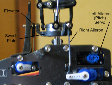
Elevator
One of the Cyclic Servos controls the
center point of the swash plate. This is the swash plate linkage
centerline with the main shaft. Either directly in front of or behind
the main shaft.
Fig
22
End Point
Controls Servo Travel limits. A typical
servo can travel -30 degrees and +30 degrees from center for a total
of 60 degrees of travel. Setting the End Point value will reduce the
degrees the servo can travel.
ESC - Electronic Speed Controller
Responsible for receiving throttle
input signal from the receiver, and controlling the current to the
motor. Most ESC units also have a built in BEC that supplies
regulated DC battery power to the receivers and all devices connected
to the receiver. If the ESC does not have a built in BEC, the
receiver will require an external BEC and battery pack.
The ESC should be sized according to
the motor it will control. Motors have amp ratings as do the ESC. It
is advised to use an ESC that has a higher AMP rating than the motor.
The ESC can become very hot in
operation. If the unit gets too hot, it can damage components and
result in losing all motor and servo control. If this happens in
flight, the helicopter will crash. For this reason, many hobbyists
chose to use an external BEC so they can retain servo control in the
event of an ESC failure.
Helicopter ESC devices come with a
variety of features. Some provide logging, and more advanced
features. The basic ESC has the following features.
Brake ( causes the motor to
rapidly stop ) Recommend to be set to Off for Helicopters.
Battery Type is
automatically detected by all modern ESC units. However you still
should set it to the type of battery you are using.
Cut Off Type –
controls what the ESC will do when it reaches low battery power. For
Helicopters, you want to use the Soft-Cut option. This will cause
the ESC to reduce power to the motor gently as it reaches a low
battery power level. You will notice that it takes more throttle
stick input to maintain flight. Quickly land the helicopter under
this condition. Determine the amount of time you have been flying,
and in the future, try not to reach this condition by monitoring
your flight time.
Start Mode – controls
how fast the motor will spin up from a dead stop. For Helicopter
models, select the softest possible setting.
Timing Mode – is
based on the motor. Typically the Low setting is used for todays
electric motors, however better performance can be achieved by using
the timing for your motor. Check with the motor manufacturer for the
correct timing to use.
*Note - many ESC
devices have become damaged using the Medium timing setting with the
wrong motor. Only use the Medium timing if your motor specifies its
use. The Timing is similar to a car distributor. It will excite the
correct windings in the correct order at the right time. Check with
your motor manufacturer for the correct timing.
Feathering Shaft & Dampeners
Also called the Horizontal Shaft. The
Blade Grips connect to the feathering shaft. The feathering shaft
runs through the main head and sits inside of rubber dampeners
(sometime these are O-rings). The dampeners come in different
hardness ratings. The soft dampener is the most common for general
park flying and moderate 3D flying. Harder dampeners are used for
extreme 3D flying. The Dampeners should be greased to prevent
galling, and eventual failure. Soft dampeners transmit less stress
and vibration to the main shaft and other head components.
Fixed Pitch
A helicopter is labeled a Fixed Pitch
(FP) model when the blade pitch is set to a predetermined angle and
the rotor speed determines the amount of lift. The faster the blades
travel the more lift. Most FP models control direction (yaw and
forward / reverse) by tilting the blade holders so that one of the
blade's leading edge will dip down, and the other will dip up causing
less lift on one side, and more lift on the opposite side.
Fly Bar
The Fly Bar on the Bell & Heller
head assembly is an integral part of the pitch control. Do not
attempt to fly your helicopter without the fly bar attached and
properly adjusted.
The swashplate does not directly
control the main blade pitch. Instead, the swashplate controls the
Fly Bar control arms, and fly bar carriage. The fly bar is a
canceling device. It slows down the reaction of the swashplate input
to smooth out the input request. The fly bar will attempt to maintain
its current direction of travel. When input is applied it will begin
to adjust to the requested position thereby soothing the change. The
more weight that is added to the ends of the fly bar result in
smoother (or less responsive) transitions from the control input. As
the pilot advances their skill level and want to work in more extreme
3D maneuvers, they will move the weights closer to the main shaft, or
remove them entirely. Fly bar paddles are rated in weight. The
Extreme 3D pilot will use very light weight and rigid fly bar paddles
such as Carbon Fiber versions. The purpose is to eliminate as much
weight as possible (to a limit) for extreme 3D flight.
The fly bar setup is correct when:
The paddles are the same size and
weight, with the same length and leading edge contour.
Are exactly the same distance from
the main shaft.
Weights are the same, and exactly
positioned the same distance from the main shaft.
The fly bar moves freely up and
down. Link balls with too much resistance will hamper the operation
of the fly bar assembly. If they are too tight, use a link ball tool
to remove burs and excess material from the plastic ball socket to
provide the fly bar free movement.
Gain
The Gyro uses a voltage gain to
increase or reduce the sensitivity of the gyro to lateral movement in
Head Holding Mode. Too much gain will result in the tail rapidly
wagging from side to side. Too little gain and the tail will wag
slowly from side to side, or fall out of Head Holding mode.
The rule of thumb is to adjust the gain
until you obtain a rapid tail wag, then reduce the gain until it
stops wagging then reduce the gain by an additional 5~10 %.
Gyro
A device that is placed between the
receiver input, and the tail servo. Its purpose is to assist the
pilot in maintaining a steady tail position in flight. In Head
Holding Mode, the gyro will remember its last “Non” input
position, and attempt to bring the tail back to that position if
something such as wind has cause the tail to move off of position.
Rate mode is similar to HH mode in that
it will counter external forces such as wind, and try to keep the
tail in one position. Rate mode does not have the previous position
memorized and will only provide servo adjustment based on the amount
of external force movement detected. After countering the external
force movement, rate mode will return the servo back to its (servo)
center position which may not be the original tail position.
You can determine if the gyro is in HH
mode by moving the tail, and the tail slider will move to one side
compensate, and it will stay in that position until the tail is
returned to the original position. In Rate mode, you will notice the
tail slider will move to compensate, but once you stop moving the
tail, it will return to center even though the tail is not back in
the original position.
Jesus Bolt
There are two Jesus bolts on a main
shaft. One at the top and one at the bottom. The top bolt holds on
the Head assembly, and the bottom bolt holds the Gear assembly. The
term “Jesus bolt” came from the last words spoken by the
pilot before the helicopter crashes due to a Jesus bolt failure.
Lift
If the fluid is air, the force is called an aerodynamic
force. An airfoil is a streamlined
shape that is capable of generating significantly more lift than
drag.[2] Aerodynamic lift is commonly
associated with the wing of a fixed-wing
aircraft, although lift is also generated by propellers;
helicopter rotors; rudders,
sails and keels
on sailboats; hydrofoils;
wings on auto
racing cars; wind turbines and
other streamlined objects. While common meanings of the word "lift"
suggest that lift opposes gravity, lift can be in any direction.
When an aircraft is flying straight and level (cruise)
most[3] of the lift opposes gravity.
However, when an aircraft is climbing,
descending, or banking
in a turn, for example, the lift is tilted with respect to the
vertical.[4] Lift may also be entirely
downwards in some aerobatic manoeuvres,
or on the wing on a racing car. In this last case, the term
downforce is often used. Lift may
also be horizontal, for instance on a sail
on a sailboat
Non-streamlined objects such as
bluff bodies and plates (not parallel to the flow) may also
generate lift when moving relative to the fluid. This lift may be
steady, or it may oscillate due to
vortex shedding. Interaction of
the object's flexibility with the vortex shedding may enhance the
effects of fluctuating lift and cause vortex-induced
vibrations. - WIKIPEDIA
In layman's terms the leading edge of
the air foil (the blade) is contoured to produce a small amount of
drag over the blade as what is occurring under the blade. This causes
the blade to have more pressure under the blade. As the blade changes
its angle of attack (Pitch) the pressure increases under the blade
causing the blade to move away from that pressure. A positive blade
pitch will produce more pressure on the bottom side of the blade
lifting the helicopter upwards.
Locktite
A chemical compound that bonds to the
material is is applied to fill the non tensioned space between
threads on a screw. The filling of the thread space reduces the
potential for vibrations to release the spring tension of the threads
thereby maintaining the original torque applied to the threads.
It is recommended to use the Blue
Locktite compound on all metal to metal screws. Blue Locktite has a
lower heat tolerance than Red Locktite.
This allows hobbyists to use a small amount of heat on a screw
treated with Blue Locktite to break down the bonding capacity of the
compound and extract the screw.
Use of a soldering iron for 10 ~15
seconds on the thread tension area is enough to break down the
compound and allow for screw extraction.
*Note – Never let Locktite come
in contact with plastic parts. The compound will weaken the plastic
as it bonds. Locktite can also scar carbon fiber materials if it is
allowed to bond and harden on the carbon fiber material.
Main Shaft
The vertical shaft that is attached to
a drive gear on one end, and the Rotating head assembly on the other
end. Main shafts can be purchased in different metal densities. The
harder shafts usually have a higher carbon composition, and are
heavier. Soft main shafts bend easier than the harder shafts. The
harder shafts do not flex as much as the soft shaft, therefore the
harder shafts provide very accurate head spin. The down side of the
harder shafts is they weigh more, and are less forgiving in a crash.
Some hobbyists believe it is better to use a soft main shaft, and let
it bend in a crash and possibly save other more expensive components.
Mixing
Provides the ability to assign a switch
or another channel input to influence the signal on another channel.
Typically used in the FS-CT6A radio to assign the Gyro Gain VR(B)
dial to channel 5.
Fig
23
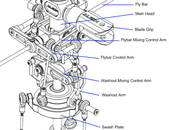
Mixing Control Arms
There are four mixing arm controls on a
Bell Heller configuration (Fig. 23). The two at the lower section
translate swash plate input through the Washout arms to the Washout
Mixing Control Arms then to the Fly bar Control Arms which rotate the
fly bar paddle pitch.
The upper set of mixing arms translate
swash plate input through long links to the Fly bar mixing control
arms that are then connected to the Main Blade Grips.
Pitch
The angle of leading edge of an air
foil (the blade). Neutral or zero pitch provides no lifting
capability. As the pitch angle increases, the air pressure on one
side of the blade surface increases to produce Lift (see Lift above)
or lateral movement (for tail blades).
Pitch Curve
A pitch curve is a set of 5 or more
points measured at equal distances for the full travel of the input
device (the joy stick). The Radio will calculate the signal strength
between each reference point.
Pitch Gauge
A tool used to measure the blade angle
from a reference level (the fly bar).
Radio Binding
The process of connecting the radio
identification signal with the receiver in wireless applications.
Receiver
Wireless Electronic radio component
that receives signals from a radio frequency transmitter. Signals are
distributed to separate channels of the receiver to control other
electronic devices.
Reverse – Servo direction settings
The configuration option to reverse the
polarity of the input signal to an electronic device such as a servo.
Rod Linkage
A mechanical component consisting of
one or more connector points that is used to transmit torque and
direction between to points. Make sure you have the same number of
threads showing on each end.
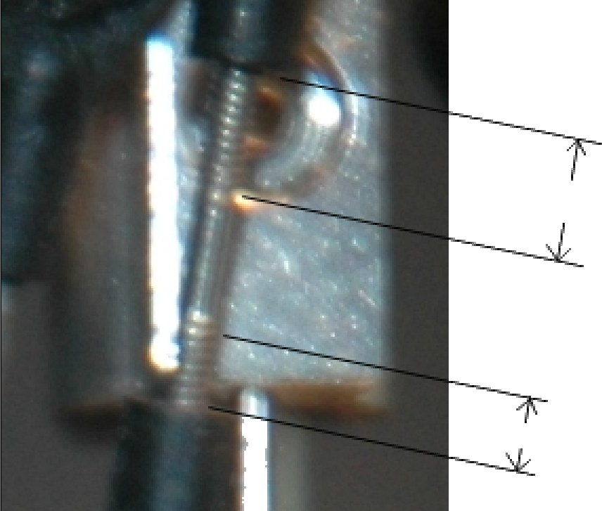
Fig
24
As a minimum, you want 5 or more
threads (turns) screwed into each plastic ball link end. Figure 24
shows an link rod that should be adjusted. The easiest way of
adjusting the link is to use a set of needle-nose pliers to rotate
the rods at the non-threaded center portion of the rod. You can make
this adjustment with the rod installed on the helicopter.
RTF – Ready To Fly
A packaged model claimed to be ready to fly out of the box. This
is a myth. Always check every fastener for tightness, proper assembly
and alignment, and that all metal to metal fasteners have the proper
amount of Blue Locktite applied. Check that all linkages and bearings
move smoothly, and there is no binding anywhere. I have experienced
Locktite in bearings, missing screws, loose screws, and missing parts
on both kits and RTF models. There have been many new hobbyist who
actually slap a battery into their new model, and man the controls
only to find out that their RTF model became Ready To Fix, or Refuses
To Fly out of the box.
Rudder
A mechanical device that is used to
steer or change the rear position of a movable object. Helicopters
use a variable speed and typically variable pitch set of blades to
provide lateral tail movement by varying the speed and pitch or
direction of the tail blades.
Serial Port
Computer In/Out port used to
communicate with external devices. Two way communications are
provided through a serial protocol (one byte at a time).
Servo
Electronic device that takes a digital
or analog signal and convert it so mechanical movement.
Servo Binding
Servo binding occurs when the servo
movement is stopped before the requested servo position request has
been completed. Servo binding can result in damaged servo gears,
overheating of servo electronics, and servo failure.
Servo Horn
A mechanical connection between the
servo output and the linkage that it controls. There are four basic
servo inner hub configurations measured by number of splines and
diameter. The servo horn may be a lever design or a circular design.
The purpose of the device is to transfer rotating movement to a
linear movement for controlling linkage.
Sub Trim
Provides small incremental adjustments
to the signal level to a servo. It will cause the servo position to
change by small degrees.
Swash Afr
Used to adjust swash plate travel up
and down and direction.
Swash Plate
The intermediate control device whose
level is transmitted to the fly bar for controlling pitch and yaw of
a helicopter.
Tail Slider Control
A mechanical device that is connected
by a rod linkage to the tail servo and tail rotor grips. Its purpose
is to change the tail rotor blade pitch to produce lateral thrust.
Test Stand
A tool that allows for mounting the
helicopter for testing under power without the potential for
crashing. Some test stands provide vertical movement for safely test
hovering the aircraft.
Throttle Curve
A throttle curve is a set of 5 or more
points measured at equal distances for the full travel of the input
device (the joy stick). The Radio will calculate the signal strength
between each reference point.
Torque Tube / Shaft Drive
A Shaft driven also called a Torque
Tube driven tail rudder uses a shaft to power the tail rotor blades.
The advantages of a shaft driven tali rotor is smoother operation
with less noise. The down side of this type of drive system is the
cost for replacement parts.
Washout Arms
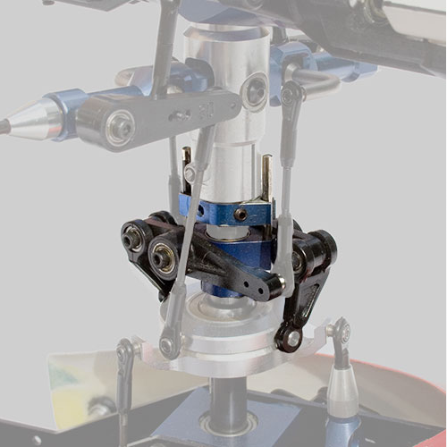
Fig
25
The washout
assembly (or lower mixer) is a set of linkages in the rotor head that
serve to mix out collective pitch inputs from the swashplate, and
pass the remaining cyclic pitch inputs to the flybar control arm.
The washout
assembly consists of three parts:
The washout guide
(often also the phase ring) that keeps the washout aligned with the
rotor head;
The washout arms
that connect the swashplate to the flybar control arm linkages;
The washout base to
which the washout arms are mounted, and which slides up and down the
main mast.
The washout also
often serves to rotate the cam follower of the swashplate with the
rotor head.
A few helicopters
do not have a traditional washout, and either transmit collective
inputs to the rotor head via a push rod separate from the swashplate
(such as the Falcon 3D), or use a flybar that can move up and down
inside a guide (such as the Gazur Mars).
Washout also refers
to changing blade pitch or profile along the length of a rotor blade,
as the tip of the blade is moving much faster than the root.
Typically model helicopter blades don't have this type of washout, as
the blades are symmetrical to allow for inverted flight.
Yaw
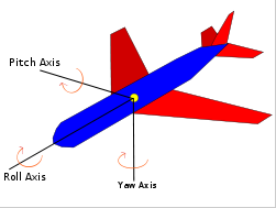
Fig
26
Yaw axis is a vertical axis
through an aircraft, rocket,
or similar body, about which the body yaws;
it may be a body, wind, or stability axis. Also known as yawing
axis.
The yaw axis is defined to be
perpendicular to the body of the
wings with its origin at the center of gravity and directed towards
the bottom of the aircraft. A yaw motion is a movement of the nose
of the aircraft from side to side. The pitch axis is perpendicular
to the yaw axis and is parallel to the body of the wings with its
origin at the center of gravity
and directed towards the right wing tip. A pitch motion is an up or
down movement of the nose of the aircraft. The roll axis is
perpendicular to the other two axes with its origin at the center
of gravity, and is directed towards the nose of the aircraft. A
rolling motion is an up and down movement of the wing tips of the
aircraft. - WIKIPEDIA
Prev
Next - Tid Bits